
From a physical effect to a product someone can buy.
Engagements range from a two-week feasibility study to owning the technical development of an instrument end to end. Most projects touch several of the blocks below — they are separated here for clarity, not because they are sold separately.
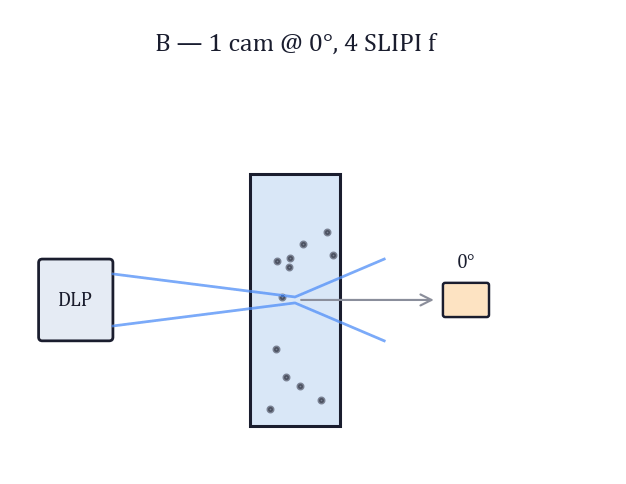
Optical design & simulation
Deciding what the instrument should look at, how to illuminate it, and how much signal will actually reach the detector.
- Illumination and detection architecture, including structured and multi-angle schemes
- Radiometric and signal-to-noise budgets, before anything is bought
- Monte-Carlo radiative transfer modelling in scattering and absorbing media
- Source, optic, filter and detector selection, with tolerance analysis
- Optomechanical layout, alignment strategy and stray-light control
- Rapid optomechanical prototyping by 3D printing — mounts, sample cells, housings and alignment jigs iterated in days rather than in supplier lead times
Algorithms, models & AI
Turning a raw detector signal into a number that survives contact with a reference method.
- Calibration models, baseline and scattering correction, spectral preprocessing
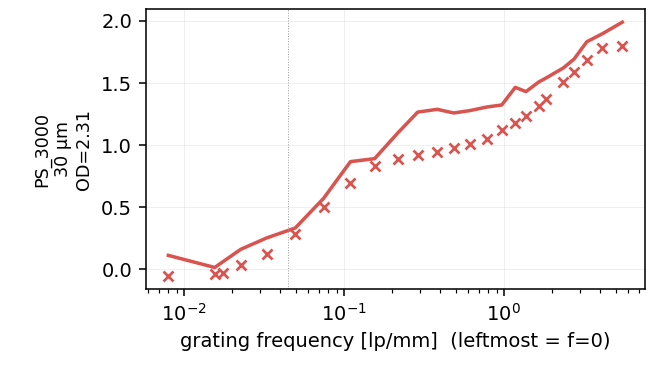
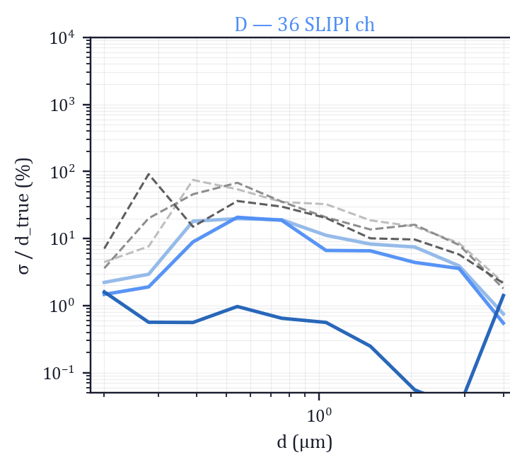
- Inverse problems: particle size distributions, concentrations, multi-component unmixing
- Chemometrics (PLS, PCA) and machine-learning models, including on-device inference
- Uncertainty quantification — what the number is worth, and when it should not be trusted
- Benchmarking against established reference instruments, on real samples
Software & embedded systems
The code that runs the instrument, on the bench and in the field, without someone watching it.
- Instrument firmware and real-time acquisition, on microcontroller and Linux-class targets
- C++/Qt and Python applications: acquisition, processing, operator UI, service tooling
- On-device inference and signal processing under real timing and memory constraints
- Data logging, export formats and interfaces for downstream analysis
- Test benches, automated calibration routines and production test software
Integration & industrialisation
Getting the instrument out of the lab and into a process that will not adapt to it.
- Industrial protocols and buses: Modbus, 4–20 mA, Ethernet, OPC UA, MQTT
- PLC, SCADA and historian connectivity, including soft-sensor deployment
- Mechanical, thermal and environmental integration for industrial conditions
- Prototype to production: design-for-manufacture review, test strategy, CE-readiness support
- Commissioning, field validation and handover to the customer’s own team
Feasibility & technical advisory
The cheapest part of a project is finding out early that it will not work — or exactly how it will.
- Feasibility studies: is the measurement physically possible on this sample, and at what accuracy?
- Technical due diligence on optical technologies and measurement claims
- Design and architecture review of an existing instrument or development programme
- Technology scouting, patent-landscape reading and R&D roadmapping
- Acting as the embedded technical lead for teams with no in-house optics function
Not sure which of these you need?
That is a normal starting point. Describe the problem and we scope it together.
Describe your problem